Everyday, we hear about AI and various surveillance systems that are used in homes, businesses and the government to monitor everything that we do. I’ve been wondering if I could make use of these AI and imaging technologies to put together an affordable robot for the elderly. Perhaps a robot to provide companionship as well as look out for their safety around the home.
It would be nice if the robot could see, hear and sense the environment it is in and react appropriately. Turn on the light when it is getting dark, turn on a space heater if it gets too cold, watch for intruders, turn on TV for the news, play games, provide reminders, connect with friends or relatives, summon for help if needed, etc.
This is not quite the humanoid robot that we have all dreamed about that can do the dishes. That, I believe, is still a bit further off. The robot I am thinking about is a companion that is there around the clock. Whereas, a regular home attendant, for example, is just there to do the house work and leaves.
Perhaps you can think of other applications for a Home Robot as well.
State of Current Home Robots
Before diving into developing my own robot, I went and did a quick survey of what is currently available. There are a lot of them. Enough to write a whole story just about it. Below, I only listed a few representative ones that are on the market.
In the past few years, many home robots have been cropping up. They range from just a table top companion robot like the ElliQ to the ORO Petcare Companion Robot that showed up in CES 2024 to take care of your beloved doggie.
And, don’t forget Amazon’s household robot Astro that would roam around the house to check what you need to order from Amazon. The Astro was announced in 2021 but still seems to be in the “purchase by invitation only” mode.
None of these robots seem to meet my requirements. Each has some of the features I am looking for but not all together in one single product. Alternatively, I would settle to get a robot that I can develop and run my own program on. However, that does not exist either.
In the end, I decided to take a shot at building a robot of my own. Actually, what I need is a Home Robot Platform to build up whatever robot I want it to be.
Key Considerations in Building the Home Robot Platform
The following are some of the key considerations in building the robot platform:
- The robot should be affordable for any tinkerer, like myself, to build
- The components in the robot should be the best that is affordable and uses the latest technology available
- The design should be easy to understand and replicated by others
- While the robot must have Wi-Fi capability, it should be fully functional without internet connection
- The robot will not send any data out unless there is explicit consent from the user
- The robot’s software will be open source
- The robot will be a modular design to allow for future upgrade and growth
After researching the components available and experimenting with some proof of concept tests, I came up with something that seems quite feasible to meet my requirements.
The Brain Behind the Robot
Since the goal is to build an affordable robot, I looked for a low cost computer board to be the brain of the robot. I also wanted to have a fully capable computer system with a lot of support.
The main processor board selected for the home robot platform is the Raspberry Pi 4B with 8GB RAM. The robot will be upgraded to the latest Raspberry Pi 5 in the future. This new Raspberry Pi 5 processor board has up to three times the performance improvement and many other upgrades for about the same price as the Raspberry Pi 4B.
The Raspberry Pi runs on the Debian-based standard Raspberry Pi OS with Raspberry Pi Desktop.
Sticking with Raspberry Pi OS ensures that reliable support is available for all the common peripherals such as sound input/output, touch screen, serial devices, external memory etc. With the popularity of the Raspberry Pi, there are a lot of affordable compatible peripherals to choose from.
To enable direct connection to devices, the Raspberry Pi has a row of GPIO (general-purpose input/output) pins along the top edge of the board for controlling specialized hardware such as servo motors or sensors.
The Raspberry Pi system comes with Ethernet, Wi-Fi and Bluetooth connectivities. Programs can be developed and executed on the robot via a headless setup over the Wi-Fi network. Unlike a regular computer, the keyboard, mouse and monitor do not need to be physically connected to the Raspberry Pi.
One of the key factors for setting up the Raspberry Pi to run the standard Raspberry Pi OS, a Linux distribution, is that it supports multitasking. This allows the robot to be doing multiple things at the same time.
The tradeoff is that activities might not be executed at the precise timing as intended. Intelligent functions could take some “thinking time” which is probably acceptable for the robot. Time-critical functions are expected to be handled by the peripheral processors appropriately.
Program for the Brain
Python is used to program the main functions of the robot. Python is a general purpose and easy to understand programming language. It is “natively” supported for the Raspberry Pi. Python can be used to control pretty much everything on the Raspberry Pi including the GPIO pins.
There is a large collection of standard Python libraries available to reduce development effort.
Python is an interpreted language. A python program can be edited and executed immediately without the need to compile and link as other programming languages such as C or C++. This makes programming the robot more fun and intuitive.
With the ease of programming, Python could potentially pose a performance issue if used exclusively for all robot control functions. This is handled in two ways.
First, the main program written in Python is primarily the “conductor” of the robot functions. It does the logical analysis and the non-real time functions. Any speed demanding behaviors that need to run on the Raspberry Pi can be written as Python callable functions in a compiled language such as C or Rust. As a newer language, Rust appears to be getting a lot of attention and support. So it might be the preferred language to use.
Second, one of the key architectural concepts of the robot is to distribute the heavy duty and real-time processing to the peripherals.
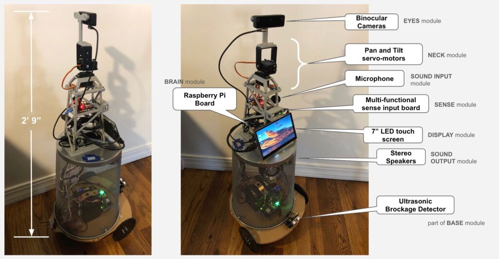
I Can See You
Just like a human, the robot uses two eyes to see and determine the distance of objects. These two eyes only see black and white. There is a third eye that can see color at high resolution. In the path of the three eyes’ output, images can be routed, processed and analyzed at high speed.
This is done with the OAK-D Lite USB module with 3 cameras on it. The OAK-D Lite has two monochrome cameras for object distance detection, a color camera for high resolution imaging and an Intel Movidius Myriad VPU for processing acceleration. These are all included in one hardware package at a reasonable cost.
In terms of control, software imaging pipelines can be developed for different needs. The DepthAI package is used by the Raspberry Pi to connect to, configure and communicate with the OAK-D Lite device.
For proof of concept, an imaging pipeline routing appropriately cropped and scaled images to various neural network models has been developed. Locations of people in front of the robot and their corresponding face signatures are detected in the pipeline. This data is continuously sent to the Raspberry Pi as a concise text stream. This allows the Raspberry Pi to understand what is going on and to determine the appropriate actions to take without expending a lot of processing power.
Pipelines was also built to identify and extract image data for specific objects such as people, faces or hands in parallel with the data text being streamed out. Analyzing targeted image data will reduce the image processing requirement for the Raspberry Pi to perform.
One application example is for the Raspberry Pi to send the cropped and scaled image data to the MediaPipe software library to perform tasks such as pose, facial landmark or hand gesture estimation.
Pose estimations can be used to determine if a person has fallen. Facial landmark estimations can be used to determine a person’s mood. Hand gestures can be used as a person-to-robot command interface. Applications are limited only by one’s imagination.
The robot currently uses the lowest cost OAK-D Lite but can be upgraded to the OAK-D Pro that uses projected IR (infrared) dots for more accurate 3D measurements and night vision to allow the robot to operate in complete darkness.
Robot Dreams
Besides the accelerated processing done on the OAK-D-Lite, much more image and video processing can be done with the Raspberry Pi processing using OpenCV. OpenCV has the world’s largest computer vision library. It can be used to do many background image analysis for the robot’s brain when it has spare compute cycles.
Also, video can be recorded from the day time and OpenCV can be utilized to extract helpful information. One example would be to analyze the previous day’s activities to note where things were placed to help find them in the future.
Sensitive to The Environment
Besides being able to see, it would be desirable for the robot to be able to hear and make sense of the sound around it. Would be useful if the robot can actually understand some spoken commands.
While there are many speech to text services offered on the internet, the intention is not to rely on having connections to the internet for the robot to function. This also removes any privacy concerns regarding sending voice data to an external entity.
The SENSE module consists of an Arduino Nano 33 BLE Sense board to analyze snippets of sound input using its on-board nRF52840 processor. The processor can be trained to recognize a small set of 1 sec sound input snippets. The training is performed with the Edge Impulse web based machine learning and deployment tool.
Communication with the Arduino Nano 33 BLE Sense is over the USB serial interface from the Raspberry Pi.
For proof of concept, the SENSE module was trained to recognize around 10 spoken phrases. More can be added. It is also possible to train the board to recognize voices and other noises such as glass breakage or large “thump” sound from falling objects.
Besides the microphone, the Arduino Nano 33 BLE Sense board also has a 9-axis Inertial Measurement Unit (IMU) to measure motions, a proximity/ambient light/color/gesture sensor, a barometric pressure sensor and a temperature/humidity sensor.
These sensors could be used to add more capabilities to the robot in the future.
It Is Not a Robot if It Can’t Move
There are only two moving capabilities on the robot. First, the NECK module allows the EYES module to be tilted and/or panned. Second, there are the wheels on the BASE module that allows the robot to move forward, move backward and turn.
The NECK module consists of two servo motors mounted on a pair of pan tilt brackets. The servo motors are driven by a servo motor driver controlled by the Raspberry Pi via I2C lines. This allows the robot to look up or down and left or right.
The BASE module has 3 wheels. There are a couple of 120 mm plastic wheels balanced by a third caster wheel in the back. The plastic wheels are driven by a pair of 98 RPM geared DC motors. These motors are controlled by its own processor from an Arduino UNO board fitted with a 2-channel Motor Driver Arduino Shield. Communication with the Arduino UNO is over a separate USB serial interface from the Raspberry Pi.
All speed and directional controls for the wheels are self-contained in the BASE module.
For safety, the UNO board independently detects objects that might have come in front of the robot with an Ultrasonic Sonar Distance Sensor mounted on the BASE module. Forward motion is stopped immediately by the UNO’s processor when an object is detected.
The BASE module is a collection of mechanical and electronic components mounted on a circular piece cut out from a 12×24” plexiglass. I got most of my wheels, motors and mounting parts from ServoCity.
There are too many miscellaneous mechanical parts to list here. If you follow the links for the DC motor and wheels, you should be able to find all the parts you need to mount the motors and wheels.
Selecting the motors, wheels and working through all the various mounting options was new to me. When I got started, I did not know where to begin. Luckily, I came across a couple of good teachers. Paul McWhorter’s Robot Training series got me started to learn about controlling servo motors. DroneBot Workshop’s Build a REAL Robot series gave me a more hands-on practical guide to select the wheels, motors and mounting hardware. Paul and Bill are very good teachers and I highly recommend anyone interested in building robots watch their series of videos.
To be able to move untethered, the robot is powered by a hefty 12V battery. The 12V output drives the DC motors and is also stepped down with multiple USB Buck voltage converters to provide power for all the boards.
Wheels are Optional
Conceptually, the BASE module is intended to be a stand alone replaceable unit that provides locomotion and battery power for the robot.
The top part of the robot includes the Raspberry Pi and all its peripherals including the speakers that are currently mounted inside the BASE module. When the top part is plugged into an AC outlet, it turns into a stationary robot with all the intelligence.
The BASE module’s function is to provide locomotion for the robot. Alternatively, the BASE module can have 4 legs, or even 2 legs, instead of wheels as long as it can understand the move commands and provide power for the top part of the robot.
3D Printed Parts on a Trash Can
The concept of the robot is that a person in the sitting position can comfortably interact with it. To get the robot to be at a reasonable height, we need to build up the robot. Also, I need to have a way to hold down all my proof-of-concept piles of parts that were taped on various cardboard boxes into an actual moving robot.
Luckily, my brother-in-law, Bob, is a retired Electrical Engineer who got into 3D printing. He is my collaborator for the robot. Bob designed the camera mount, the “tower” and all the miscellaneous bits and pieces to hold things together. It is amazing what one can do with a 3D printer. Maybe I can talk Bob into sharing his experience of how to get into 3D printing and the details of the 3D parts used to build the robot.
With the limitation of the size of printable 3D parts, we really needed something bigger to prop up the robot and to provide it with some stability.
Inspired by the Daleks, which many thought looked like a moving garbage can, we headed to Home Depot looking for a similar “body part”. Lo and behold, we found an office trash can that fits the bill. The wired trash can, mounted upside down on top of the plexiglass, serves as a cover for all the electronics, battery and wires of the BASE module.
The bottom of the trash can, when it was flipped over, provided a flat surface to mount the top part of the robot. For convenience, we have decided to mount the speaker inside the trash can for now.
In the future, we could come up with a 3D printed BASE module enclosure design that would reduce the parts needed to mount the wheels and would be easier to assemble.
Rounding it Off with the Usual Computer Peripherals
Besides the specialized peripherals, there is a 7” touch screen, a USB microphone and a pair of stereo speakers connected to the Raspberry Pi. With these accessories, many applications can be built from scratch or based on existing open source projects.
Here are some examples:
- One can build interactive games using the touch screen.
- With the screen and microphone, one can build robot-to-robot video calls using the open source code like Jitsi.
- Another idea is to have a follow-me kind of game to entice a person to do exercise while following sequences of arm postures. Captured image information can be analyzed. Player’s correct pose sequence scores points.
With mobility, the robot can move right next to you for calls or move to the appropriate distances for games or other applications.
The Robot is a Complete Development Environment
I was totally hooked when I first played with an Apple II computer. I could write and execute Basic code right from the keyboard with the built-in editor. The results appeared immediately on the screen. With the color graphics support, I could create pictures interactively. That kind of feedback was extremely empowering and inviting for exploration. I wanted the same development environment for the robot.
There is a minimum set of tools required to develop capabilities for the robot. All software development tools run on the Raspberry Pi. These tools can be remote accessed from any computer or laptop via Virtual Network Computing (VNC), the headless setup as mentioned before. Changes made on the robot can be tested directly without relying on any other external devices.
Python programming can be done with the pre-loaded Thonny editor or with a downloaded free Visual Studio Code for a more powerful code editing.
OAK-D Lite imaging pipelines are Python snippets on the main program that are downloaded onto the OAK-D Lite device.
The Arduino Nano 33 BLE Sense and the Arduino UNO boards are programmed with the Arduino IDE that runs on the Raspberry Pi.
With the Raspberry Pi Desktop, windows to program the main Raspberry Pi processor and the peripheral processors using the Arduino IDE can be shown simultaneously on the same screen.
Where is the LiDAR and ROS on the Robot?
For those who have been reading about robots, many of these robots have a LiDAR (light detection and ranging) device. Many robots also run on top of ROS (Robot Operating System).
LiDAR (Light Detection and Ranging) technology senses the reflection of a scanning light source as it is bounced off objects to produce a 3D map of their surroundings. Perhaps not at the same accuracy, the depth detection stereo camera on the OAK-D Lite can do the same function at a much lower cost.
ROS is not really an Operating System as such. It is more like a framework designed for robotics software development. It’s a collection of libraries and tools that operates on top of a conventional operating system such as Linux. While ROS allows for expandability and has a large support community, it requires a substantial level of overhead to set up and operate. In my opinion, ROS is more suited for industrial applications.
Conclusion
Except for the 3D printed parts, all components were purchased off the shelf. Total cost of the material is less than US$700. This is still expensive and takes quite a bit of effort to assemble.
While there are some areas where cost can be reduced and new 3D designs can be done to consolidate or replace current mechanical parts, the final cost will not be reduced too much. Besides, there are at least two functions that need to be added that will increase the cost.
Currently, the robot needs to be charged manually. We are in the process of adding some 3D printed hardware and sensors to design a charging home port for the robot. Cost is to be decided.
Also, the Raspberry Pi uses a microSD card for program storage. This should be upgraded to use a more reliable SSD memory. Luckily, the new Raspberry 5 supports booting from and using SSD memory. This could add about $150 to the robot.
However, the Prototype 1 design is a good start. Even without further work, the current robot is a good platform to be used to start exploring robot functionalities.
With the help of ChatGPT, I have the modular software architecture defined. I have a basic functional robot up and running. But there is a lot more to do.
In the mean time, I am also studying up on various AI concepts to see how they can be deployed on the robot. The fun is just starting.
If there are interest, I could provide more details on the various aspects of the robot’s design in future stories. Please let us know.
You might want to build one yourself too. It would be interesting to see how far we can get with such a robot if more people worked on it together.